
Light is a form of energy which travels as an electromagnetic wave. We have already discussed the reflective properties of waves in the previous article about waves, light waves also reflect when they touch an opaque surface. We use light rays for this because these are easier to observe.
Reflection of Light
Lig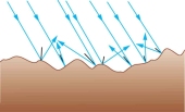 ht waves follow the same principle as any other wave. When a few parallel light waves strike a smooth, flat surface, it will change direction and move away from the surface, in parallel rays. This is the principle of reflection.
On a rough surface the light rays do reflect but they will be more scattered. The rays will not be parallel to each other.
If a light ray impacts on a plane mirror, which is opaque, then the light will reflect. An imaginary line is formed perpendicular to the surface of the mirror at the point where the ray touches the surface, this straight line is called the normal.
The ray moving towards the mirror is called the incident ray which is incident on the plane mirror and the ray moving away from the mirror is the reflected ray.
The angle formed between the incident ray and the normal is called the angle of incidence, i.
The angle formed between the reflected ray and the normal is called the angle of reflection, r.
The angle of incidence and the angle of reflection is always equal.
Images formed By reflection
When you place a candle in front of the mirror and then look towards the mirror you will be able to see an image of the candle.
An image can be either real or virtual. A virtual image cannot be projected on to a screen. If you place the same candle in front of the wall you will notice that no image is formed on the wall.
A real image can be projected on the a screen. If you place a projector in front of  the wall, and add the tape, then turn on the projector, it will form an image on the wall.
To you, it will appear as if the image is coming from behind the mirror although it is not true. In a diagram, we will show the rays as dotted lines that form the image behind the mirror.
In a diagram, you have to create two rays of light and at the point where the two rays converge an image is formed. Since the image is not really behind the mirror we will say that the image is virtual.
The virtual image will be of the same size as the object from which the light rays are coming from and it will be inverted (it will be back to front) and also will be at the same distance from the mirror as the object.
Refraction of light
All waves can reflect and refract. The reason waves refract is because of the sudden change of speed. Light waves travel fastest in vacuum, while it travels in about the same speed in air as in vacuum.
When it enters another transparent medium or substance that is more dense than the medium light is originally travelling in, the light wave slows down and then changes its direction. This change in direction is called refraction.
If you place a transparent glass block on a platform and point a laser light on to it at an angle the light will refract.
You can create a normal here where the light touches the glass block. Measure the angle of incidence. In case of refraction, the angle of refraction is used, which is in between the refracted ray and the normal.
A point to be noted is that when light enters a denser medium from a less dense medium, the angle of refraction will always be smaller than the angle of incidence.
When the light wave moves from more dense to a less dense medium, its angle of refraction will always be greater than the angle of incidence.
If the light ray is moving straight, perpendicular to the glass block surface, then it will not refract but pass through.
The refractive property depends upon the thickness or, more importantly, the refractive index, n, of the medium that light travels in.
The refractive index is the ratio of the sine of the angle of incidence to the sine of angle of refraction: n = sin i/sin r. This equation is called Snell’s Law which is named after the Dutch scientist Willebrord Snellius known mainly as Snell.
The refractive index of a medium determines the angle of refraction of the light ray. The higher the refractive index, the angle of refraction will always be smaller than the angle of incidence.
If the refractive index is low, then the angle of refraction will be larger than the angle of incidence.
Total internal reflection
When light enters a less dense medium it has a greater angle of refraction than angle of incidence. When the angle of incidence increases then so will the angle of refraction.
 There comes a point when the angle of refraction becomes 90°. At this point the angle of incidence is called the critical angle.
If the critical angle is further increased then the light will obey the laws of reflection. This is because when the light refracts, there is still a small amount of light that is reflected of the surface of the denser medium.
The light at this point is completely reflected which is why this situation is called the total internal reflection.
To find the critical angle we use the equation, c=1/n. c represents critical angle, 1 represents the sine of angle of refraction because angle of refraction is always 90 and sin(90) is always equal to 1, n represents the refractive index.
Lenses
Lenses can either be concave or convex. These lenses have different refractive properties.
The convex lens tend to cause parallel rays of light to refract and converge at a certain point. The concave lens causes parallel rays of light to refract and diverge.
The point at which the lens converge, an image is formed, and this point is also known as the principle focus or focal point. The distance from between the focal point and the lens is called the focal length.
The image formed might be real or virtual depending upon the lens as well as the distance at which an object is placed. In a concave lens, the image formed is always virtual, because the image appears to be coming from across the lens.
We will make dotted lines to see the light converge at a certain point, even though this convergence is imaginary, this will still become a focal point.
Ray diagrams
To understand this, we can also make a ray diagram. The y-axis of the ray diagram is the lens and the x-axis will be the principle axis.
If an object is placed in front of the lens, light rays will bounce off the object and enter the lens and then refract.
The point at which the light rays will pass through the principle axis, that point will be the principle focus or focal point.
The length from this point to the lens axis will be known as the focal length. The image will always be formed below the principle axis if the image is real.
To construct the light beams on the diagram, make a light ray from the object to  the lens axis parallel to the principle axis and then from the lens axis change its direction towards the principle axis.
Make another ray of light straight through the optical center (the point at which the principle axis and the lens axis meet). This ray of light will not refract at all.
You can also make a third ray of light on the diagram straight through the principle axis, it should touch the lens axis and then it will refract and move parallel to the principle axis.
Real Image formed on ray diagrams
The point at which these rays of light converge, an image is formed. Mark the length of this point to the principle axis and this will be the magnification of the image.
To find the magnification of the image formed we will divide the length of the image to the length of the object. With this we can say that magnification is the ratio of the height of the object to the height of the image; m = hi/ho. m is for magnification, hi is for height of image, ho is the height of object.
We can also find magnification by dividing the distance of the image from the lens to the distance of the object to the lens; m=v/u. v is for distance of image while u is for distance of object.
The height of the image formed will depend upon the distance of the object from the lens. If the object  is at the focal point, the image formed will be of the same size as the object.
If the object moves away from the focal point the image will magnify. If the object moves away twice the focal length, the image will diminish.
Virtual Images formed from Lens
In a ray diagram, if you move the object closer to the convex lens, then the rays of light will refract but will not converge, to an observer the image formed will be at the back of the lens.
On the diagram we would draw dotted lines towards the back of the object to a point where the light rays will converge, here an image is formed, since this is the point where the light is seemingly coming from (it’s not actually) this will make a virtual image which is magnified.
 A concave lens causes the parallel beam of light to diverge. Because the parallel beam of light diverges, straight dotted lines (to represent the imaginary rays of light) are drawn from the diverged rays to converge them on the left of the ray diagram above the principle axis.
The point where the light converges, that point is where the virtual image is formed.
