Salam (May God Bless You). Today I have brought to you the article based upon the electromagnetic spectrum which consists of a 7 transverse waves. I will also briefly describe the applications of the waves known to be in the electromagnetic spectrum.
The Visible Light Spectrum
In 1686, Sir Isaac Newton placed a prism shaped glass block in front of sun light and determined that he could see almost 7 different colors.
If we observe, then the light coming from the sun or a lamp is a white light. This white light tends to disperse into the 7 different colors.
This dispersion is due to refraction of the light. Why this happens is because the white light is an electromagnetic wave and thus have the property of a wave, it seems to have various wavelengths.
Because of having different wavelengths, each wave refracts at different rates, this causes the beam of light to seperate into 7 separate beams of light.
In a rectangular glass block the light beams tend to refract back together when it exits the block but the geometry of a prism causes the light beams to refract more.
The red light refracts the least while the voilet ray of light refracts the most compared to other light beams.
A point to note is that there is no gap or a clear boundry between these rays of light which is why this is called a continuous spectrum.
You should know that the red light has a longer wavelength while the voilet light has the smallest wavelength compared to others.
These waves travel at the same speed in air and in a vacuume; 300 000 000 m/s, which is called the speed of light.
Since the speed is always the same, the increase in wavelength causes a decrease in frequency. The decrease in wavelngth causes an increase in frequency. 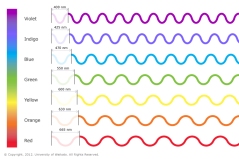
These wavelengths are so small that we use the term nanometer to measure the wavelengths of the waves. Fun Fact is that humans can only see 400 to 700 nm wavelengthsand those who cannot differentiate between these wavelengths are called colorblind.
To test this we use the equation mentioned in previous articles; v = fλ. You will notice the result as you calculate.
Electromagnetic Spectrum
The electromagnetic spectrum consists of the electromagnetic waves which are transverse waves.
These are emitted by the sun. Part of these series are; Gamma rays, X-rays, Ultra-voilet, Visible Light, Infra-red, Microwaves, Radiowaves.
 The rays of light are also in a continuous spectrum as in the case of visible light. The Gamma ray has the shortest wavelength but the highest frequency while the radiowaves have the longest wavelength but have shortest frequency.
These waves also travel at the same speed, the speed of light.
The energy each wave can transfer depends upon the wavelength and the frequency of the wave. A short wavelength can transfer more energy than those with a longer wavelength and a wave with higher frequency can transfer more energy while the waves with shorter frequency cannot transfer much energy.
The Gamma Rays can transfer more energy than any other wave in the spectrum while the radio waves transfer far less energy.
The word Ultra-voilet means “beyond voilet” meaning that the frequency of the waves on this side is higher than the voilet ray of light in the visible light. Infra-red means “below red” meaning that the frequency of these waves are lower than red.
Applications of The Electromagnetic spectrum
The electromagnetic spectrum has proved its uses over the years.
Gamma rays are emitted by the decay of radioactive nuclei. It is useful mainly in the medicinal sector, where these waves are used for different purposes. One of which is that the rays are used to make pictures or diagrams of organs because it penetrates the skin easily and can be detected. It is also used to treat cancer. These rays are very dangerous to living tissue which makes them excellent for killing cancerous cells. These rays are also used to detect cracks in metals of a building or an object where it is impossible to do so.
 The X rays are also used in the medicinal sectore, these are also capable to penetrate human skin but are stopped at the bones which are much harder than human flesh. This is useful to make Xray diagrams of bones to detect injury.
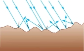
The Ultra voilet rays are very harmful to living tissue. Most of it is reflected off the Earth’s Surface, but our bodies have a further protection in our skin. Our skin has a pigment called melanin which gives our skin its color. It absorbs the Ultravoilet rays and do not let them enter the flesh. The Ultra voilet rays are used in SunBeds to tan our skin, the waves causes our skin to produce more melanin.
Visible Light is very useful today, it is the very source of light in the darkness of night time and is also used in fiber optics to transfer large bits of data around.
The infra-red are rays emitted by a hot object. The hotter an object the more infra-red rays it will emit. These rays have small range  of wavelengths and frequencies. It is used in many household applications such as alarm detectors which detect a change in heat energy which is detected by these rays. These rays are also used by your t.v remote which sends signals to the t.v, each button has its own frequency and a little difference in wavelength in the infra-red waves.
The Microwaves are not reflected or absorbed by the Earth’s atmosphere. This makes it useful for sending signals across the space, and to the sattelites.
 Radio waves are reflected by the Earth’s atmosphere, this is why these are used in communications. The waves can travel over the horizon, to large distances making it useful for contacting someone across the country.
With this I end this Article.

 ht waves follow the same principle as any other wave. When a few parallel light waves strike a smooth, flat surface, it will change direction and move away from the surface, in parallel rays. This is the principle of reflection.
 the wall, and add the tape, then turn on the projector, it will form an image on the wall.
 the medium light is originally travelling in, the light wave slows down and then changes its direction. This change in direction is called refraction.
 There comes a point when the angle of refraction becomes 90°. At this point the angle of incidence is called the critical angle.
 refract and diverge.
 formed is always virtual, because the image appears to be coming from across the lens.
 the lens axis parallel to the principle axis and then from the lens axis change its direction towards the principle axis.
 is at the focal point, the image formed will be of the same size as the object.
 A concave lens causes the parallel beam of light to diverge. Because the parallel beam of light diverges, straight dotted lines (to represent the imaginary rays of light) are drawn from the diverged rays to converge them on the left of the ray diagram above the principle axis.
 moving from their positions but vibrating, transferring their kinetic energy to the other particle. If you tie a rope to a wall and grab the other end and move it up and down continuously, you would see a wave produce on the rope while the rope itself does not move towards the wall even though the kinetic energy is being supplied to the wall.
 of wave is if you attach a spring with a wall and then grab the other end and move the spring forward and backward continuously. You will notice a series of compression and rarefaction formed in the spring which are properties of the longitudinal wave.
 a longitudinal wave the wavelength is calculated by measuring the distance from the middle of a compression to the adjacent middle of the compression or from the middle of the rarefaction to adjacent middle of the rarefaction.

 seen in ripple waves. If these waves touch a straight wall which is at an angle from the waves, the waves would then reflect to another direction. An imaginary straight line is made at an from the point at which the waves touch the wall, this is called the normal, the angle formed from the normal and the direction of the waves is called an angle of incidence. The angle formed from the normal and the point of reflection is called the angle of reflection.
 taken from the ripple waves. If a wave moves from deeper water to shallower water then the wave slows down and then refracts. This is because when the front part of the wave touches the shallower water it slows down, and then the rest of the wave follows up and slows down as well and this continues on while the wave refracts.
 suggested. Place a hard flat surface. Place a clock with a wide tube reaching towards the flat surface. Then place another tube at the adjacent side of the other tube and listen through the tube. You should hear the clock ticking.
 refraction happens in between the layers in the atmosphere. During day time the ground air becomes warmer while the air high up is colder which is why sound waves refract up wards. At night the air in ground is cold while the air high up is warmer causing the sound waves to refract downwards.